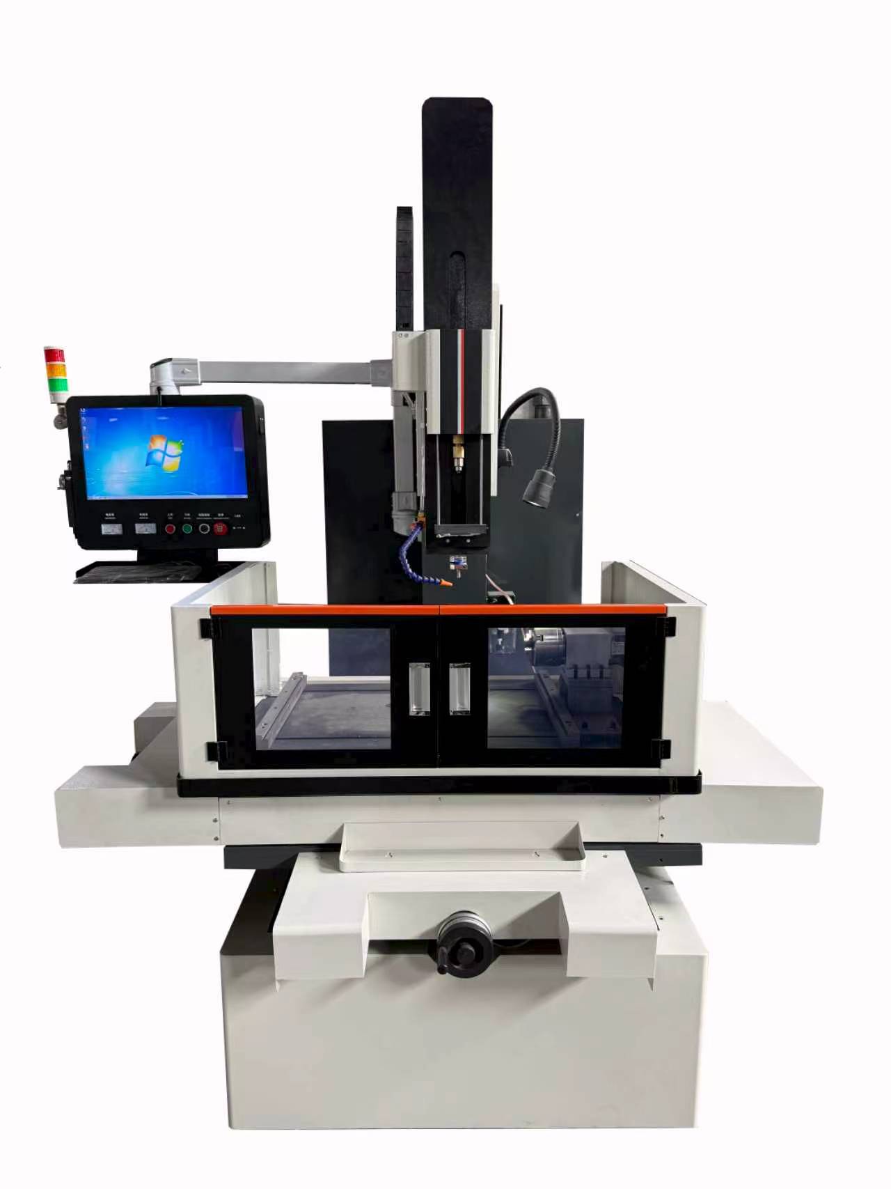
What Is the Cutting Machine Working Principle Explained
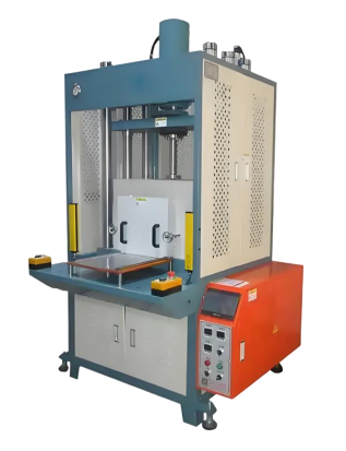
Overview of Cutting Machine Technology
Cutting machinery equipment is engineered for blanking and forming applications, giving manufacturers a reliable way to transform raw material into finished parts with controlled shear force. As a category, this equipment spans servo-driven, hydraulic-driven, and pneumatic-driven systems, along with a dedicated roll-knife configuration for continuous processing of roll materials. Understanding how a cutting machine works is essential for manufacturers evaluating blanking solutions, and the underlying principle remains consistent across the product range even as the drive technology changes to match different production needs.
The General Working Principle
At its core, a cutting machine uses a power-driven actuator to apply shear force to material through a cutting tool, separating the material according to set dimensions to complete blanking and forming. In practical terms, the equipment relies on an electric motor, oil cylinder, or air cylinder as the power source to drive the cutting die downward. This downward motion applies shear force to the material resting on the worktable, cutting the workpiece into the required shape. For applications demanding tighter tolerances, precision models are typically equipped with a vacuum adsorption platform that prevents material shifting and stretching during the cutting cycle, ensuring the finished part matches the intended dimensions.
This working principle applies broadly, but the specific mechanism used to move the press plate downward differs depending on whether the machine uses servo, hydraulic, or pneumatic power, or whether it is configured for continuous roll-knife cutting.
Power Drive Types and Their Mechanics
Servo drive: A servo motor drives a lead screw or crank mechanism, moving the press plate downward smoothly. Pressure, speed, and depth are closed-loop controllable, resulting in low impact and high precision during the cutting process.
Hydraulic drive: A hydraulic pump station delivers pressure oil to push the cylinder, moving the press plate downward. This configuration produces large-tonnage output force, though pressure precision is slightly lower than servo systems, and oil temperature fluctuation can affect pressure consistency.
Pneumatic drive: A cylinder uses compressed air to push the press plate downward for punching. This approach features a simple structure and low cost, with average pressure precision suited to less demanding applications.
Roll-knife drive: A servo motor drives upper and lower counter-rotating knives, shearing material continuously during feeding. This method is suitable for high-speed mass production of roll materials, where uninterrupted cutting is required.
Material Handling and Positioning Systems
Before the cutting action begins, material handling and positioning play a critical role in achieving accurate results. A vacuum adsorption platform holds the workpiece or material on the worktable to prevent shifting and stretching; this feature is standard on precision models and configurable on selected types. For applications requiring additional accuracy during feeding, CCD visual alignment is available as an optional feature for servo cutting machines, supporting precise positioning before the cutting die engages the material.
The Cutting Execution Process Step by Step
The cutting execution process follows three consistent stages regardless of drive type:
- Press plate downward movement: The press plate moves downward, driven by servo, hydraulic, or pneumatic power depending on the machine type in use.
- Cutting die pressure application: The cutting die presses the material and applies controlled pressure to separate it according to the set dimensions.
- Part and waste separation: After cutting, the press plate rises, and the finished part is separated from the waste material, completing the cutting cycle.
This sequence—downward pressing, controlled shear, and separation—forms the operational backbone of cutting machinery equipment across all drive configurations.
Product Lineup Matching Different Needs
Cutting machinery equipment is offered across four distinct product lines, each addressing a specific production requirement.
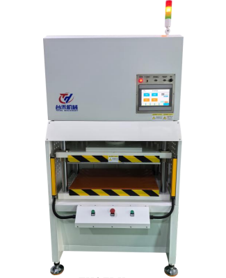
The Servo Cutting Machine is positioned for precision cutting of easily deformable materials such as thin films, MEA, and carbon paper. Because these materials can shift, stretch, or become damaged when cutting force, speed, and depth are not precisely controlled, this product relies on closed-loop control of pressure, speed, and depth. The workpiece is placed on the worktable and fixed by vacuum adsorption, with optional CCD visual alignment available. The servo motor drives a lead screw or crank mechanism for stable, low-impact pressing, and the cutting die applies accurate, controllable pressure in one pass before the press plate rises to complete the cycle.
The Hydraulic Cutting Machine is built for large-tonnage punching of thick materials, foam, and gaskets. Material is placed on the worktable, with vacuum adsorption available as a configuration option. The hydraulic pump station delivers pressure oil to the cylinder, generating large-tonnage pressure to punch and break the workpiece, after which the cylinder returns oil and the press plate rises to reset for the next cycle.
The Pneumatic Cutting Machine serves simple blanking tasks where precision demands are not high. The cylinder relies on compressed air to push the press plate downward for punching, applying shear force to separate material into the required shape at a low cost with a simple structure.
The Roll-Knife Cutting Machine addresses continuous cutting of roll materials for high-speed mass production. The servo-driven upper and lower counter-rotating knives shear the material continuously during feeding, supporting uninterrupted output that intermittent cutting methods cannot efficiently achieve.
Matching the Right Cutting Machine to Production Needs
Because material characteristics and production volume vary widely, the choice between servo, hydraulic, pneumatic, and roll-knife cutting machinery depends on the specific application. Easily deformable precision materials benefit from the closed-loop control offered by servo-driven equipment, while thick materials, foam, and gaskets require the large output force of hydraulic systems. Simple blanking jobs with limited precision requirements are well served by pneumatic-driven machines, and roll materials destined for high-speed mass production are best handled by roll-knife continuous cutting systems. This differentiated product matrix allows cutting machinery equipment to address blanking and forming needs across a wide range of material types and production scales, without relying on a single drive technology to solve every application.
Conclusion
The working principle of a cutting machine centers on using a power-driven actuator—whether an electric motor, oil cylinder, or air cylinder—to move a cutting die downward and apply shear force to material positioned on a worktable, separating it into the required shape. Precision models further support this principle with vacuum adsorption platforms that prevent material shifting and stretching. By offering servo, hydraulic, pneumatic, and roll-knife configurations, cutting machinery equipment covers the full spectrum of blanking and forming requirements, from delicate thin-film precision cutting to large-tonnage punching and continuous roll-material shearing, giving manufacturers a technically grounded basis for selecting the right cutting solution for their material handling and production goals.
wwww.gdthjx.cn
Taihe Machinery
About Author